Assessment of Shear Operation Tegular Unreinforced Beam and Reinforced Beam Under Monotonous Loads
Ehsan Elyasi1 * and Roxana Montazerian2
1
Department of Civil Engineering,
Razi University,
Kermanshah,
Iran
2
Department of Architecture,
Razi university,
Kermanshah,
Iran
http://dx.doi.org/10.12944/CWE.10.Special-Issue1.13
Brick buildings are the oldest constructional systems that have been prevalently constructed during the time. As appropriate knowledge about performance of these constructions is very important in optimizing, improving and developing them against inserted loads, we investigated cutting manner of brick beams as a specific element in brick buildings. The samples were under steady state loading at the middle of opening. Both beams were claps at both ends. Samples were studied in two conditions of reinforced armatures (in lengths) and without reinforced armatures. The results revealed about 7 times increase in loading capacity and about 6 time increase in maximum place change of the beam. It was resulted that cracking start and development was same in both samples but depend upon value of inserted loads.
Firstly, experiments were performed on constructional materials in accordance with ASTM standards in order to determine type of mixtures and pressure strength of mortar on brick units.
Copy the following to cite this article:
Elyasi E, Montazerian R. Assessment of Shear Operation Tegular Unreinforced Beam and Reinforced Beam Under Monotonous Loads. Special Issue of Curr World Environ 2015;10(Special Issue May 2015). DOI:http://dx.doi.org/10.12944/CWE.10.Special-Issue1.13
Copy the following to cite this URL:
Elyasi E, Montazerian R. Assessment of Shear Operation Tegular Unreinforced Beam and Reinforced Beam Under Monotonous Loads. Special Issue of Curr World Environ 2015;10(Special Issue May 2015). Available from: http://www.cwejournal.org/?p=10486
Download article (pdf)
Citation Manager
Publish History
Introduction
As there are many brick building in Iran, and such structures are highly vulnerable to the earthquake, a good understanding of the behavior of structural elements and components of these structures might contribute to improve their performance. Note that due to the low cost of materials, there are more prevalent in rural areas and small towns.
Therefore, this study is aimed to determine and asses the behavior of beam in a brick building. To do so, the performance of brick shear beam is evaluated under monotonic loading in two modes of non-reinforced and reinforced with bars.
In addition to review the results by other authors, the present paper majorly is to test the masonry wall.1,2,3 For instance, Najib Esmaeil et al.1 studied the behavior of masonry wall diagonal sections non-reinforced and reinforced with high-strength stainless steel bars, which are placed near the wall surface. The study measured the failure modes, shear strength, maximum displacement and shear modulus, which resulted in the increase of 114 - 189% in the shear strength. In present study, it is also performed several compression tests to determine the best behavioral performance of masonry components. It should be noted that all the study materials and mortar compositions are like the ones utilized in the construction of masonry buildings in the geographic area of the research.
Compression Tests on Masonry Component
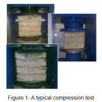
The compression test is performed on different compositions of mortar in accordance with the standards of ASTM [4] for masonry walls. To do so, the masonry components are built in quadruple and triple rows (see Figure 1). Then, the compression tests are performed on them, while the loading rate of samples is 5 mm per minute. The results are given in the following tables :
Table1: The material specifications used in the compression tests
|
Ratio |
w/c |
Cement weight (gr) |
Sand weight (gr) |
Lime weight (gr) |
Sample dimensions (mm) |
P(kN) |
||
|
1 : 3 |
0.6 |
2500 |
7500 |
0 |
204.5 |
100.5 |
131.2 |
55 |
|
1 : 0.5 : 4.5 |
1.1 |
3000 |
13500 |
1500 |
200 |
102.3 |
132.6 |
55 |
|
1.1 |
3000 |
13500 |
1500 |
204 |
97.5 |
131.1 |
65 |
|
|
1 : 1 :6 |
1.5 |
2500 |
15000 |
2500 |
207.2 |
96.44 |
215.4 |
50 |
|
1.5 |
2500 |
15000 |
2500 |
208 |
109.1 |
203.1 |
40 |
|
|
1.5 |
2500 |
15000 |
2500 |
190.4 |
91.1 |
215.8 |
38 |
|
|
1 : 1 : 6 |
1.3 |
2500 |
15000 |
2500 |
203 |
97.3 |
277.3 |
45 |
|
Ratio |
w/c |
Cement weight (gr) |
Sand weight (gr) |
Lime weight (gr) |
Sample dimensions (mm) |
P(kN) |
||
|
1 : 3 |
1 |
2500 |
7500 |
0 |
214.4 |
201.1 |
98 |
42 |
|
1 |
2500 |
7500 |
0 |
217.2 |
201 |
96.1 |
44 |
|
|
1 |
2500 |
7500 |
0 |
216.1 |
209.6 |
103 |
55 |
|
|
1 |
2500 |
7500 |
0 |
213.3 |
201.1 |
98.4 |
49 |
|
|
1 : 0.5 : 4.5 |
1.3 |
2500 |
11250 |
1250 |
285.4 |
200.2 |
102.1 |
56 |
|
1.3 |
2500 |
11250 |
1250 |
225.2 |
206.1 |
103.1 |
57 |
|
|
1.3 |
2500 |
11250 |
1250 |
211 |
201.1 |
102.1 |
37 |
|
|
1.3 |
2500 |
11250 |
1250 |
214.1 |
204 |
103.1 |
35 |
|
|
1 : 1 : 6 |
1.5 |
2500 |
15000 |
2500 |
134.4 |
205.1 |
96.5 |
34 |
|
1.5 |
2500 |
15000 |
2500 |
223.5 |
206.1 |
97.1 |
41 |
|
|
1.5 |
2500 |
15000 |
2500 |
289 |
201.9 |
98.1 |
38 |
|
According to the previous results, it is chosen the ratios of 1:0.5:4.5 and 1:3 respectively for the mortar, and the water and cement to build the sample brick beams.
 |
|
Table 2: Test material compositions
|
Ratio |
w/c |
Cement weight (gr) |
Sand weight (gr) |
Lime weight (gr) |
Sample dimensions (mm) |
P(kN) |
σ (N/mm²) |
||
|
1 : 0.5 : 4.5 |
1.3 |
2500 |
11250 |
1250 |
285.4 |
200.2 |
102.1 |
56 |
0.98009909 |
|
1.3 |
2500 |
11250 |
1250 |
225.2 |
206.1 |
103.1 |
57 |
1.22808514 |
|
|
1.3 |
2500 |
11250 |
1250 |
211 |
201.1 |
102.1 |
39 |
0.91911548 |
|
|
1.3 |
2500 |
11250 |
1250 |
214.1 |
204 |
103.1 |
38 |
0.87003508 |
|
It should be corrected the calculated compressive stress based on the h/t ration (see Table 3), where h denotes the sample height and t indicates it smallest dimension. In this case, the corrected mean compressive stress is equal to 1 MPa.
Table 3: The Correction factors of compressive stress
|
σ(Mpa) |
h(mm) |
t(mm) |
h/t |
correction factor |
(Mpa) |
|
0.98 |
285.4 |
102.1 |
2.795299 |
1.04 |
1.0192 |
|
1.22 |
225.2 |
103.1 |
2.184287 |
1 |
1.22 |
|
0.919 |
211 |
102.1 |
2.066601 |
1 |
0.919 |
|
0.87 |
214.1 |
103 |
2.078641 |
1 |
0.87 |
Test Samples
Sample Specifications
Non-reinforced Beams
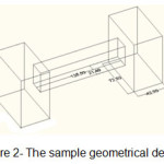
The sample non-reinforced brick beam has the dimensions of 1250 * 280 * 214 mm (see Figure 2), while its bottom distance from the ground is 250 mm with beam height of 280 mm. The mortar composition is shown in Table 2. The brick beam is mounted on two stands of the same material, each with dimensions of 420 * 720 * 750 mm (see Figure 3.1).
Rebar-Reinforced Beam Specifications
The sample reinforced brick beam has the same dimensions (see Figure 2), while its bottom distance from the ground is 22cm with beam height of 30cm. The beam is reinforced by two #10 deformed bars for each section, in three heights of 8, 16.5, and 23 cm. The deformed bars are placed a line with beam length, as well as each stand (see Figure 3.2)
 |
|
 |
|
Tests and results
Tests
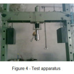
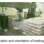
The test is performed by using a fixed jack with a nominal capacity of 160 kN and the ability to measure the force - displacement (see Figure 4).
 |
|
In both tests, a rigid plate with dimensions of 215 * 200 * 22 mm is sued for relatively monotonic distribution of concentrated load. The uniform load per unit of time is equal to the displacement of 2 mm per minute. The displacement of the center of the beam is measured. Figure 5 shows the location and orientation of the rigid plate and the loading.
 |
|
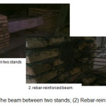
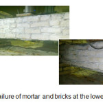
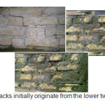
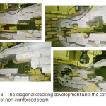
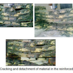
In both cases, the reactions begin with failure and detachment of first brick row (see Figure 6). In accordance with the results of other tests on masonry walls by the researchers5,6, diagonal cracks originate in the bottom of the beam and in the both ends (see Figure 7). By continuing to load the non-reinforced beam, it is seen several failures due to the development of cracks in the mortar, bricks, and also the joints between the lower and middle parts of the beam (see Figure 8). Loading is continued until a complete failure of the beam.
 |
|
 |
|
 |
|
The test on the reinforced beams is the same as beam without reinforcement, with the difference that in the test, the loading is performed in 3 steps due to the device limitations in recording the displacements of more than 55 mm. Note that the reinforcement percentage is equal to 0.0073 of the beam cross section. In the first step of loading, the failure of mortar's and bricks' joints begin at the bottom row (see Figures 7-8) much less rapidly than of the non-reinforced beam. The Figure 9 shows the detachment of material and development of cracks. In the last loading, all the material of beam are failed.
 |
|
Test Results
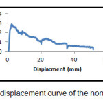
Diagram 1 illustrates the test results of non-reinforced beam. The maximum force and displacement are presented in the Table 4. The failures which are also recorded in the descending part of the curve indicate great ones. Complete failure of the beam is occurred at the displacement of 51.3 mm.
Table4: Force-displacement of the non-reinforced beam
|
Force (kN) |
Displacement (mm) |
Maximum Displacement mm)) |
|
2.87 |
2.26 |
51.3 |
 |
|
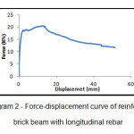
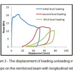
Diagram 2 corresponds to the force - displacement curve of the reinforced brick beam, while Diagram 3 shows the force - displacement curve of reinforced brick beam with loading-unloading in three steps. The data is given in Table 5.
Table 5: Force -displacement of reinforced beam
|
Force (kN) |
displacement (mm) |
Maximum Displacement mm)) |
|
20.54 |
12.78 |
77.96 |
 |
|
In the Diagram 2, there is seen a failure close to the force of 20 KN, while it is obvious a simultaneously increasing strength of all three longitudinal rebar rows.
 |
|
After three steps of loading-unloading, the deformation of masonry components is equal to 77.96 until the complete failure and detachment.
Discussion of Results
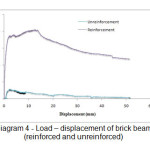
As mentioned in previous paragraphs, the main purpose of current study is investigating difference of cutting performance in beams which are and are not reinforced with longitudinal armatures. Accordingly, best mixtures were selected and model samples were prepared to test impacts of pressure on brick units in combination with different mortars and also in order to analyze results of other studies. The results indicate considerable difference in forming and loading capacity of the reinforced beam comparing to unreinforced ones (diagram no. 4). The results are summarized in table 6.
Table 6: comparing load-displacement in reinforced and unreinforced beams
|
Load (KN) |
Displacement (mm) on the basis of load |
Maximum Displacement (mm) |
|
|
Reinforced Beam |
2.87 |
2.26 |
51.3 |
|
Unreinforced Beam |
20.54 |
12.78 |
77.96 |
According to table 6, the beam’s loading capacity was increased from 2.87 KN to 20.54 KN by reinforcing the beams which is about 7 times more than unreinforced conditions. Moreover, displacement in maximum load condition increased from 2.26 to 12.78 which is about 6 times more than primary status. It is noteworthy that final displacement of the
 |
|
The experiments also revealed that formation and distribution of cracks are same in both conditions and the only difference was in value of inserted load. Therefore, other reinforcing methods such as FRP can be employed in weaker points of the beams including corners with stands in order to increase loading capacity and forming value.
References
- Najif Ismail, Robert B. Petersen, Mark J. Masia, Jason M. Ingham ;( 2011), Diagonal shear behaviour of unreinforced masonry wallettes strengthened using twisted steel bars,
- Corradi , C. Tedeschi, L. Binda, A. Borri ; (2007), Experimental evaluation of shear and compression strength of masonry wall before and after reinforcement: Deep repointing ; Department of Civil and Environmental Engineering, University of Perugia, Italy , DIS-Dept. of Structural Engineering, Politecnico of Milan, Italy ,
- Mebarki a, Q.H. Bui a, R. Ami Saada a,*, P. Delmotte b, S. Sanchez Tizapa a ; (2008), Asimplified mechanical model to assess the bearing capacity of masonry walls:Theory and experimental validation ; a Université Paris-Est, Laboratoire Modélisation et Simulation Multi Echelle, MSME FRE 3160 CNRS, 5 Bd Descartes, 77454 Marne-La-Vallée, France; b Centre Scientifique et Technique du Bâtiment (CSTB), 77447 Marne -La- Vallée cedex 2, France
- Masonry Test Methodes and Specifications for the Building Industry, standard test method for compressive strength of masonry prisms, fourth edition (2001)
- Zimmermann, A. Strauss, K. Bergmeister ;( 2010), Numerical investigation of historic masonry walls under normal and shear load ,
- Liborio Cavaleri, ,Andrea Failla, Lidia La Mendola, Maurizio Papia ;( 2005), Experimental and analytical response of masonry elements under eccentric vertical loads
- Vladimir G.Haach , Graca Vasconcelos, Paulo B.lourenco ;( 2010), Influence of aggregates grading and water/cement ratio in workability and hardened properties of mortars